Categories: Protek 608 Digital Multimeter
Tags: connectivity development electronics hardware rs-232
Posted by: Darian Cabot
Comments:2
Protek 608 RS-232 details
This post is a continuation of the Protek 608 DMM software project.
This is following on from my previous post introducing the Protek 608 multimeter and my software project. In this post I detail the communications hardware, an important consideration for future development.
The Protek 608 uses an RS-232 connection to allow for interfacing with a PC. This is a very common connection that most DMMs used. These days many DMMs have a direct USB cable, so communications will be TTL, but I suspect the protocols are much the same. I use a RS-232 to USB converter cable. I have a few of these, and they are easy to find at your local electronics or computer store, or online of course.
RS-232 connection
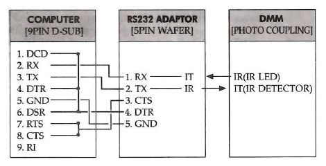
Here’s a wiring diagram from the Protek 608 manual:
If you’re not familiar with RS-232, this is a description of the signal lines labelled:
| Signal | Description |
| DTE | Data Terminal Equipment such as a computer terminal | DCE | Data Communication Equipment such as a modem | DCD | Data Carrier Detect (DCE is connected to telephone line) | DTR | Data Terminal Ready (indicates presence of DTE to DCE) | DSR | Data Set Ready (DCE is ready to receive commands data) | RTS | Request To Send (DTE requests the DCE prepare to receive data) | CTS | Clear To Send (indicates DCE is ready to accept data) |
Serial data properties
Here are the serial properties from the manual.
| Parameter | Value |
| Baud rate | 9600 | Data bits | 7 | Stop bits | 1 | Parity | None | Flow control | 'RTS/CTS' or 'DTR/DSR' not 'None' or 'XON/OFF' |
When I was first trying to read data from the multimeter I didn’t RTFM and assumed 8 data bits, as is quite common. I tried different serial programs, different USB converter, until I finally realised my mistake. 😛
RS-232 signals
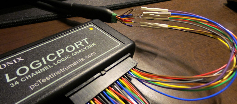
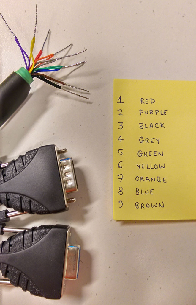
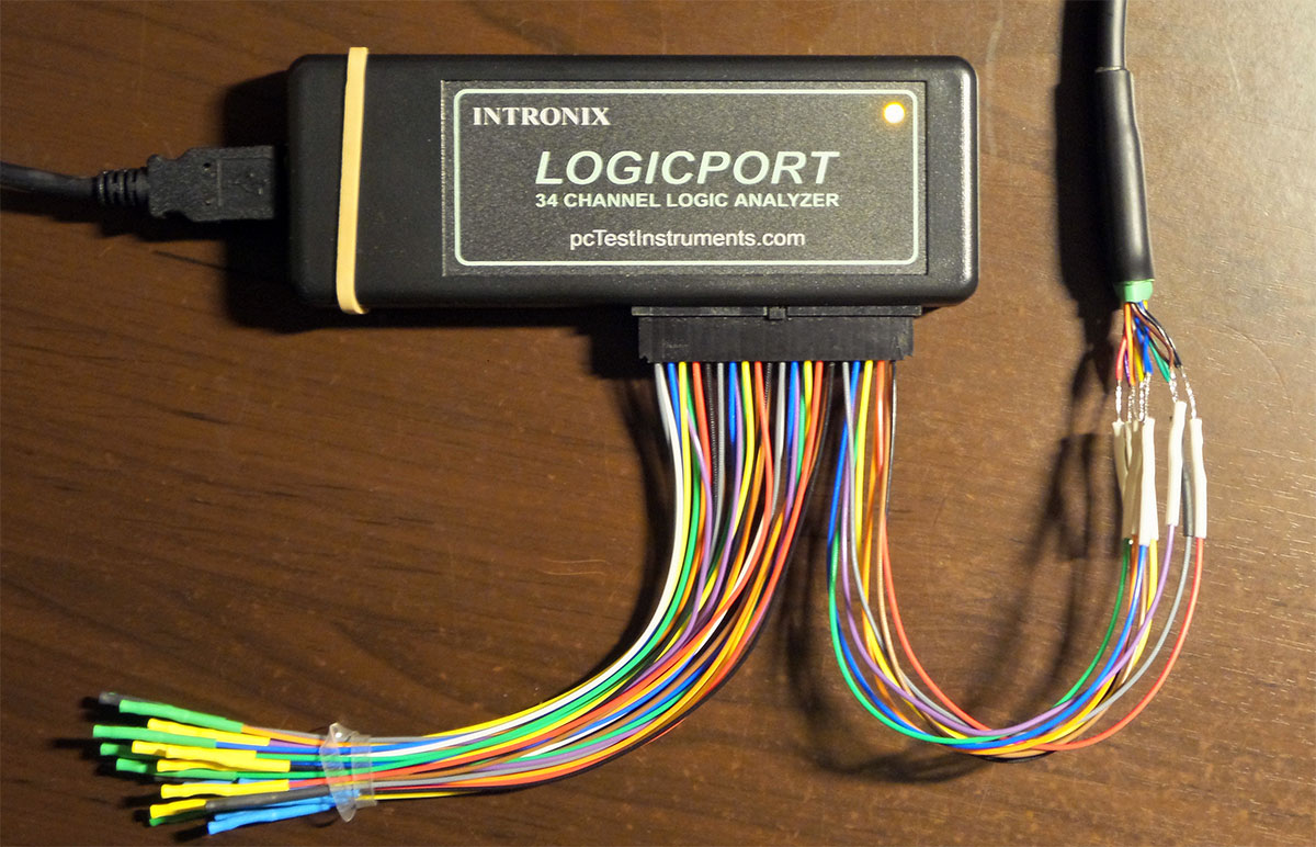
In order to measure the RS-232 signals, I cut into a standard serial cable, and tinned each wire with solder. I belled-out each pin signal with each wire colour.
This gave me a convenient connection point for each of the 9 wires. I’m using a Intronix 34-channel Logicport logic analyser. I have a bunch of little clips that I originally purchased with the logic analyser, but found that I was able to gingerly plug each signal wire to the serial cable wires directly.
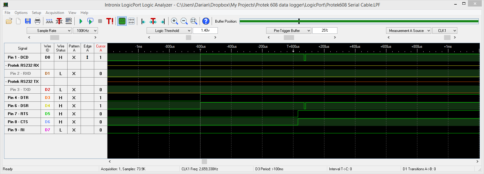
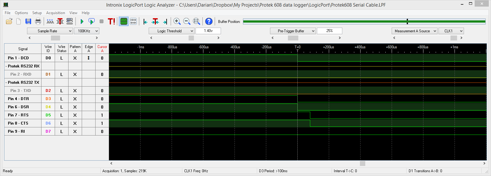
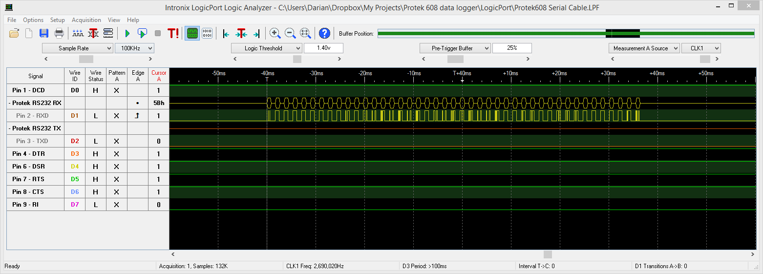
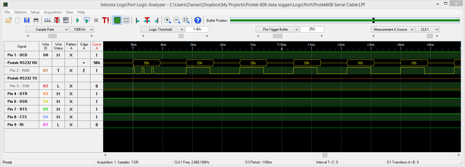
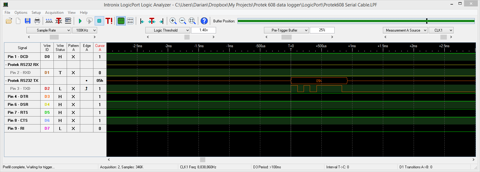
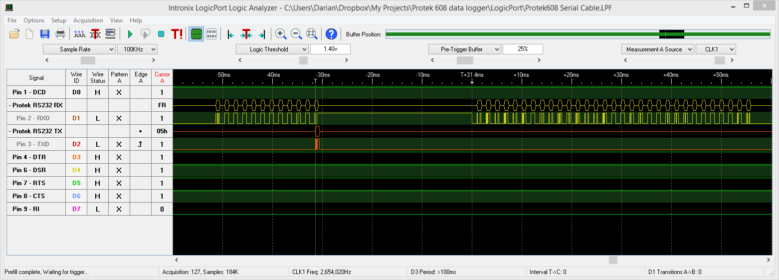
Here are a few interesting captures from the logic analyser software

2 comments
I shit You not…. I installed the windows 98 version on windows 10 and it worked!!! installed; I dont have the IR interface so cant test buttttt INSTALLED
or get this: http://www.ebay.com/itm/OWON-B35-Large-LCD-Multimeter-Bluetooth-Android-IOS-Mobile-App-Datalogger-DMM-/371696262477?epid=1946090985&hash=item568ad2dd4d:g:kJgAAOSwARZXmlon