Categories: Electronics Hardware Software
Tags: connectivity development electronics hardware modbus rs-485 software windows
Posted by: Darian Cabot
Comments:5
Eastron SDM120 power meter Modbus configuration
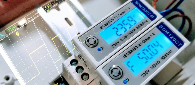
I’ve been playing with some very cheap, but quite good power meters made by Eastron for a few years now, in particular their compact (single-DIN) single phase Modbus meters. They are great for cheap (non-commercial) energy monitoring applications. The SDM120M variant has Modbus over RS-485 support for convenient data acquisition and integration.
These aren’t the easiest things to configure for Modbus communications and have a few quirks. Once you understand how to set them up, it’s quite easy. The aim of this post is to provide clear instructions on how to set the baud rate and address ready for use in the field.
Assumptions
- You are using a Windows computer
- You are somewhat familiar with COM ports and Modbus
- You are qualified to safely wire the meter
What you’ll need
- Eastron SDM120M power meter – I purchased mine from AliExpress
- FTDI USB-RS485-WE-1800-BT cable or similar USB-485 cable
- Modbus software – I used CAS Modbus Scanner for Windows. There are plenty of applications out there, but we’ll need something that can write floating-point numbers.
Wiring
Warning: this is a mains voltage device! Incorrect wiring may cause personal injury or death. Do not continue unless you are qualified and know what you’re doing!
Main power wiring
The mains wiring terminals will depend on the meter you have. The external CT meter is wired differently from the inline meter, so refer to the manual (attached below) and your specific meter. To provide and example, the mains wiring shown in the images below is for the external CT version.
RS-485 communications wiring
The table below shows how to connect the RS-485. In this case, I’m using the FTDI USB-RS485-WE-1800-BT cable, but any generic USB to RS-485 cable will work. I’ve even used the cheap $2 eBay specials successfully.
| Eastron SDM120M | FTDI USB-485 cable |
| Terminal 9 (B-) | Yellow – Data – (B) |
| Terminal 10 (A+) | Orange – Data + (A) |
| Terminal 8 (G) Optional Data Ground |
Black – Ground (I left this disconnected for this quick set-up) |
Photos


Connecting to the meter
Factory default settings:
Baud rate: 2400
Data bits: 8
Parity: None
Stop bits: 1
Address: 1
Configuration
The Modbus address and settings are done using a Modbus connection.
- Power on the meter and connect using the RS-485 to USB adaptor to your computer. You should be able to read some registers to confirm communications.
- Hold the button on the front for 3 seconds, until “-SEt-” is displayed. Now settings can be changed over the Modbus connection. If this a new meter, the default address is 1.
- Now you can change settings by writing to the Modbus registers starting from 40013 (refer to the Modbus manual linked below).
Note: The settings registers are in Float format and must be written as two consecutive registers (that is 2 x 16-bit words / 4 x bytes). For example, to set the baud rate to ‘9600’, write “2” as a float to registers 40029+40030 as defined in the manual. - Cycle power to apply the new settings.
Resources
You can download the SDM120 manual and Modbus documentation from the Eastron website, but I’ve also mirrored them here for convenience and also scanned in the insert flyer that comes in the box:
Hardware and software engineer with experience in product development and building automation. Director at Cabot Technologies and Product Manager at NEX Data Management Systems.


5 comments
darian,
do you know if the SDM120 does match to the solax X1 inverters ? what baudrate does it need ?
Thank you for this amazing post about the SDM120CT meters. What is the difference between the -M version (SDM120CT-M) I thought the SDM120CT also talked over modbus?
Hi, it’s been quite a while since I looked at this. I don’t think there was any difference. I think it’s just a different build revision (note that the terminals are also slightly different). From memory they communicated the same.
Could you fix the links to the documents? They seem to be dead, thanks 🙂
Links to attachments have been fixed. Thanks for letting me know