Categories: GPS and compass
Tags: arduino development electronics embedded hardware
Posted by: Darian Cabot
Comments:0
Home-made GPS and compass update

If you aren’t familiar with my compass and GPS project, you can find more information on this post: Home-made GPS and compass
After posting my project I had a number of questions online. I thought this is a good opportunity to update the blog to share more information on this project.
GUI concepts
I’ve made some more progress on the software side of things, mostly just playing around with the graphics display. The Nokia 3310 LCD screen I’m using is only 84 x 48 pixel resolution so a lot of forethought is required to get all the data on the screen. Another issue I noticed when testing is that the pixels aren’t square, they’re higher than wide. This means that a circle will not display perfectly round but look a little squashed. It’s a pain, but these screens are cheap ($10 including driver chip), and very reliable (if you’re familiar with old Nokia phones, you’ll know what I mean).
Below are some ideas I’ve had so far:


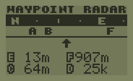


There are a few screens I haven’t designed yet like settings, data log management, etc. These concepts are by no means final and programming graphics like this can be complicated so there will no doubt be some redesigning.
Q&A
Here are some questions and feedback I received, with my responses 🙂
Dont they make an APP for that?
cleatis
Yes I believe there are several, but a smartphone is huge overhead for a simple GPS. I’m primarily interested in coordinates and headings, not anything that depends on the Internet (map directions). I believe a stand alone unit will have less hardware dependencies, will be more rugged, have greater battery life, is serviceable by myself, and does everything the way I want it… and is lots of fun to build and test 🙂
I keep environmental specifications in mind when choosing electrical components, so far it’s rated to -20°C to +70°C operational temperature – this is something I can’t control when relying on a smartphone.
I should have probably mentioned that this is a project of passion first and foremost. I’ll develop it just for my own curiosity.
Why did you use a non-tilt compensated magnetometer? Price. Pops
bearhawk
For now it’s a price thing. A tilt compensated compass module is around twice the cost of a standard module. The only draw back is the device will need to be held relatively flat for the greatest accuracy (like a real compass). I could always upgrade the compass module later without too much redesign, but I’d like to field test first. Also, I use a combination of magnetometer and GPS information for heading depending on the situation, so I do get added accuracy there for no extra hardware cost.
Does the gps have a NEMA output?
nk14zp
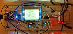
Yes! Initially I was logging with simple CVS protocol, but decided instead to use standard NMEA sentences to make the logs more compatible. Current I only log GGA sentences, other data like speed can be derived afterwards if required. I also log depending on distance and speed thresholds to avoid logging redundant data (i.e. the same coordinates when the unit is not moving). Logs are saved on a microSD card (not shown on my previous photo).
Arduino FTW! I have mine for almost 3 years now. Very cool, use it often to learn and play around with electronics. But…. isn’t a garmin easier in terms of portability and durability? Don’t wanna haul a breadboard and jumper wires in the field LOL
Dutchprep
Haha, yes, I could easily buy a Garmin, and it would save me a lot of time and money. This is a challenge for me. I love DIY and enjoy the build process. The final unit will be compact and weather/waterproof, so no breadboard… although my neighbours must think I’m a bit weird as I run around my place holding a breadboard when testing. 😉
Hardware and software engineer with experience in product development and building automation. Director at Cabot Technologies and Product Manager at NEX Data Management Systems.